
- products
- aviation
- aerospace
- consulting
- actuators
- electronics
- example 1
- example 2
- example 3
- example 4
- systems
![]()
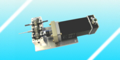
Example: landing flaps drive control unit
We have
developed a landing flaps drive control
unit. The modular design makes the drive
unit suitable for other actuation tasks.
The control unit has several features:
|
| The modular design with two
boards simplifies the operation in
different power regimes (with only minor
adaptations in the software). The
featured version operates (according to
RTCA DO-160) at 28 VDC and up to 15 A.
The adaptation to positioning tasks and requirements different to the featured landing flap is greatly simplified by the modular design. So especially for compact application with battery supplied actuation systems in research and development (as vehicles, mobile robotics) there are several exchangeable variants with common interface. |
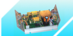
Test control unitThe first evaluation uses a test unit with more displays and configuration switches compared to the final unit. The additional means for adjustment and feedback simplify the set-up and design review considerably. |
 |
Schematic wiring diagramThe schematic wiring diagram shows the connection of the control unit with the pilot interface (with switches, buttons and LEDs) and the aircraft installation (motor, brake, limit switches). |
 |
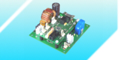
General board stackThe control unit stack consists of two boards: the large power board and on top the micro-controller board. |
 |
Individual boardsThe power board has the power stages to drive the motor and the power-off brake and various protective measures for the operation according RTCA DO-160. On the micro-controller board are the connectors for the pilot interface and also various protective measures. |
 |